3
Model
(Input___Air Flow_Max CFM)
Qty Nom. Area Qty Nom. Area
Size (in²) Size (in²)
045_30_1200 1 24x24x1 576 1
16x25x1 400
070_30_1400
1
25x30x1 750 1
16x25x1 400
070_40_1600 1 25x30x1 800 1
16x25x1 400
090_40_1600 1 25x30x1 800 1
16x25x1 400
090_50_2000 2 20x25x1 1000 2
16x25x1 800
115_50_2000 2 20x25x1 1000 2
16x25x1 800
Side Return Filters
Minimum Recommended Size
For Maximum CFM
Disposable* Permanent*
• Maximum Filter Face Velocities:
Disposable-300 ft/min
Permanent-600 ft/min
Model
(Input___Air Flow__Max CFM)
Qty Nominal
Area
Size
(in²)
045__30__1200 1 14x25x1 350
070__30__1400 1 14x25x1 350
070__40__1600 1 16x25x1 400
090__40__1600 1 16x25x1
400
090__50__2000
1 20x25x1 500
115__50__2000
1 20x25x1 500
Permanent
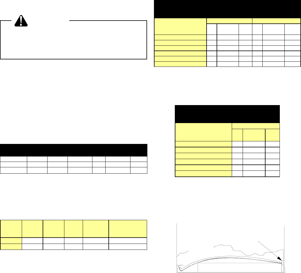
Bottom Return Filter
Minimum Recommended Size
For Maximum CFM
The figure below shows how the filter is retained over the
bottom return air opening.
FILTER
FILTER
RETAINER
FURNACE FRON
FURNACE BOTTOM
CAPTIVE LANCES
IN BACK PANEL
Cut Away Side View of Bottom Return Wire
Filter Retainer
IMPORTANT NOTES:
1. All furnaces have a redundant gas valve and blower
door interlock switch.
2. All furnaces are manufactured for use on 115 VAC, 60
Hz, single phase electrical supply.
3. IMPORTANT: While the data is presented as a guide,
it is required to properly size fuses and wires and make
electrical connections in accordance with the National
Electrical Code and/or all existing local codes.
4. Performance figures are based on Department of En-
ergy information and requirements under continuous
operating conditions. Performance will vary with weather
conditions and use.
5. Drain connections must conform to local codes.
Minimum Clearances
WARNING
To avoid death, personal injury or property
damage due to fire, clearances to combus-
tible surfaces listed as below must be
observed.
Service Accessibility and Unit Connections
• 36 inches front clearance is required for servicing or
cleaning.
• Unit connections (electrical, flue, and drain) may
necessitate greater clearances than the minimum
clearances listed below.
NOTE: In all cases, accessibility clearance must take
precedence over clearances from the enclosure where
accessibility clearances are greater.
POSITION* SIDES FRONT REAR TOP BOTTOM FLUE
Upflow 0 3 0 1 C 0
Horizontal 6 3 0 6 C 0
MINIMUM CLEARANCES TO COMBUSTIBLE MATERIALS
(INCHES)
C = If placed on combustible floor, floor MUST be wood ONLY.
* = All positioning is determined as installed unit is viewed from the front.
Standard Altitude Installations
For installations above 7000 feet, please refer to your
Amana distributor for required kit(s).
Gas Altitude Kit Orifice
Manifold
Pressure
Pressure
Switch Change
Natural 0-7000 None #43 3.5" w.c. None
Propane 0-7000 LPTK09 #55 10.0" w.c. None
Note: In Canada, gas furnaces are certified only to 4500 feet.
Flame Sensor
Flame sensor output is 1 to 4 microamps at 115 volts.
Filters
FIlters must be used with this furnace. Filters do not ship
with this furnace but must be provided by the installer.
Filters must comply with UL900 or CAN/ULCS111 stan-
dards. If the furnace is installed without filters, the warranty
will be voided.
For air delivery of less than 1800 CFM; use one side return
or bottom return ductwork connection.
For air delivery of 1800 CFM or higher: use two side return
or one side and one bottom return connection.
 (10 pages)
 Manymanuals.com
 Manymanuals.de
 Manymanuals.fr
 Manymanuals.it
 Manymanuals.pl
 Manymanuals.cz
 Manymanuals.es
 Manymanuals-pt.com
Comments to this Manuals